
This was my first Arduino project. I build a simple, battery powered, LED light that is controlled by knocking on top of it. It is pretty bright and it draws around 7W when powered. It lasts for about 3 hours when turned on.
The enclosure

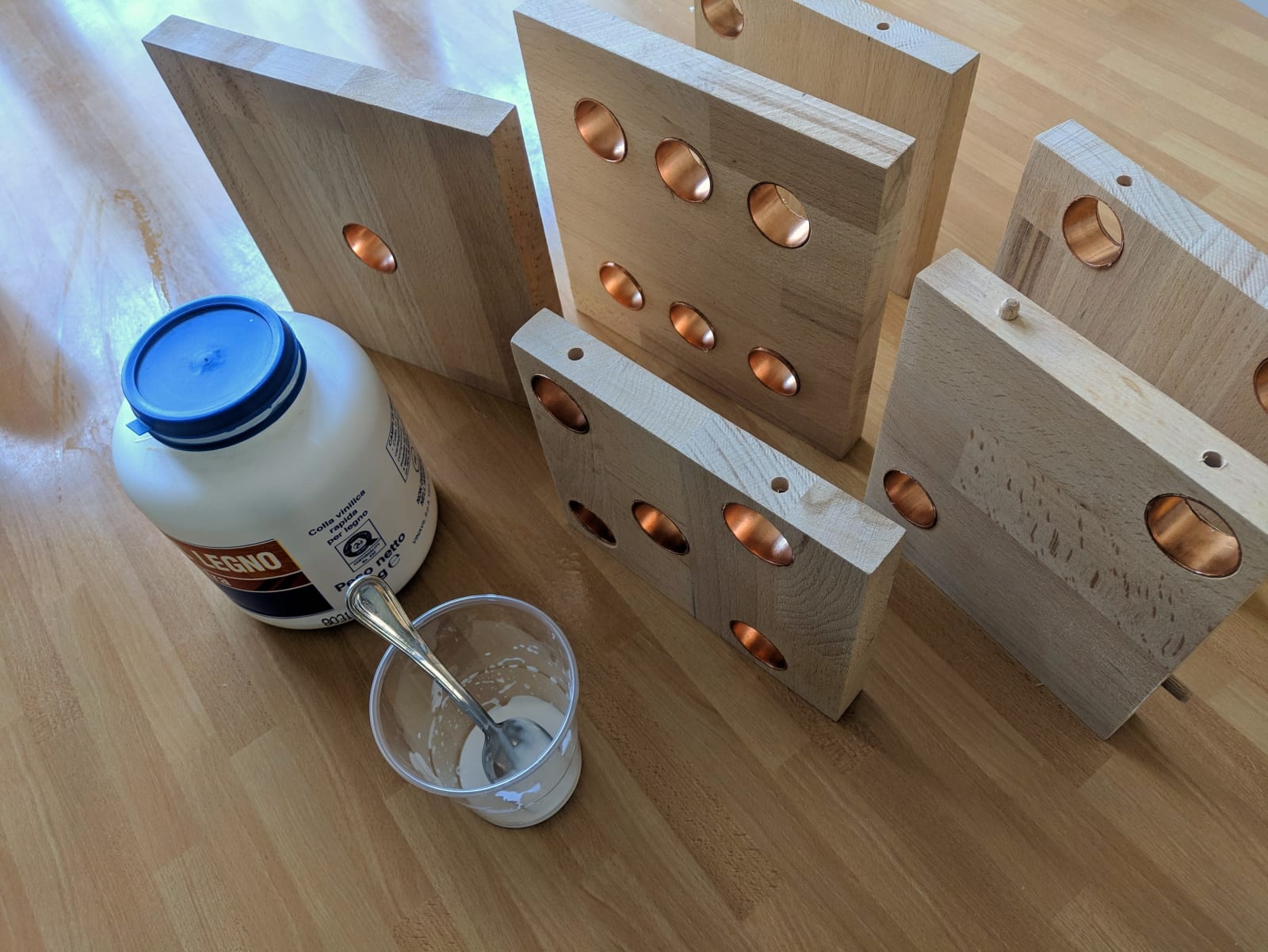
The dice is made of 20 mm beechwood. I don’t have a tablesaw yet, so I ripped down the board in smaller section with a jigsaw and a simple guide made from an aluminum profile. Overall, they turned out pretty straight. I should have set the jigsaw blade perpendicular to the board. The cube is 18 cm wide, so I cut every face accounting for the board thickness.
Next I drilled some holes for the dowels to keep everything in place during the glue-up. In hindsight, dowels weren’t really necessary. I 3D printed a simple jig to drill straight holes at a fixed distance from the edge of the board. When I drilled the last hole, the jig was basically destroyed, but it worked. If I need to do it again I will probably buy a more solid jig to use.
Next I drilled the holes. I traced the diagonals of every face and marked the center of every hole. The copper I’ve used is from 28 mm copper fittings I found at the hardware store. I ripped them in half cause they were to long using a hacksaw. I covered the inside of the copper cylinders with transparent spray paint to prevent them from oxidizing. Next I glued the in place with woodglue, but even without that it was already a pretty tight fit.
I cut a 4 mm PMMA sheet in 21 4x4 cm squares. I sanded them down with 300 sandpaper to make them matte, to make them diffuse light. I then used Acryfix plexiglass glue to glue them on the inside of the cube. I had to glue everything up: I used Vinavil Legno (500gr for 6€!) and a set of clamps. I did not glue the top face (the one with 6 holes) because I still needed to fit the electronics. I drilled a small hole for the power swith and the usb port


The Electronics
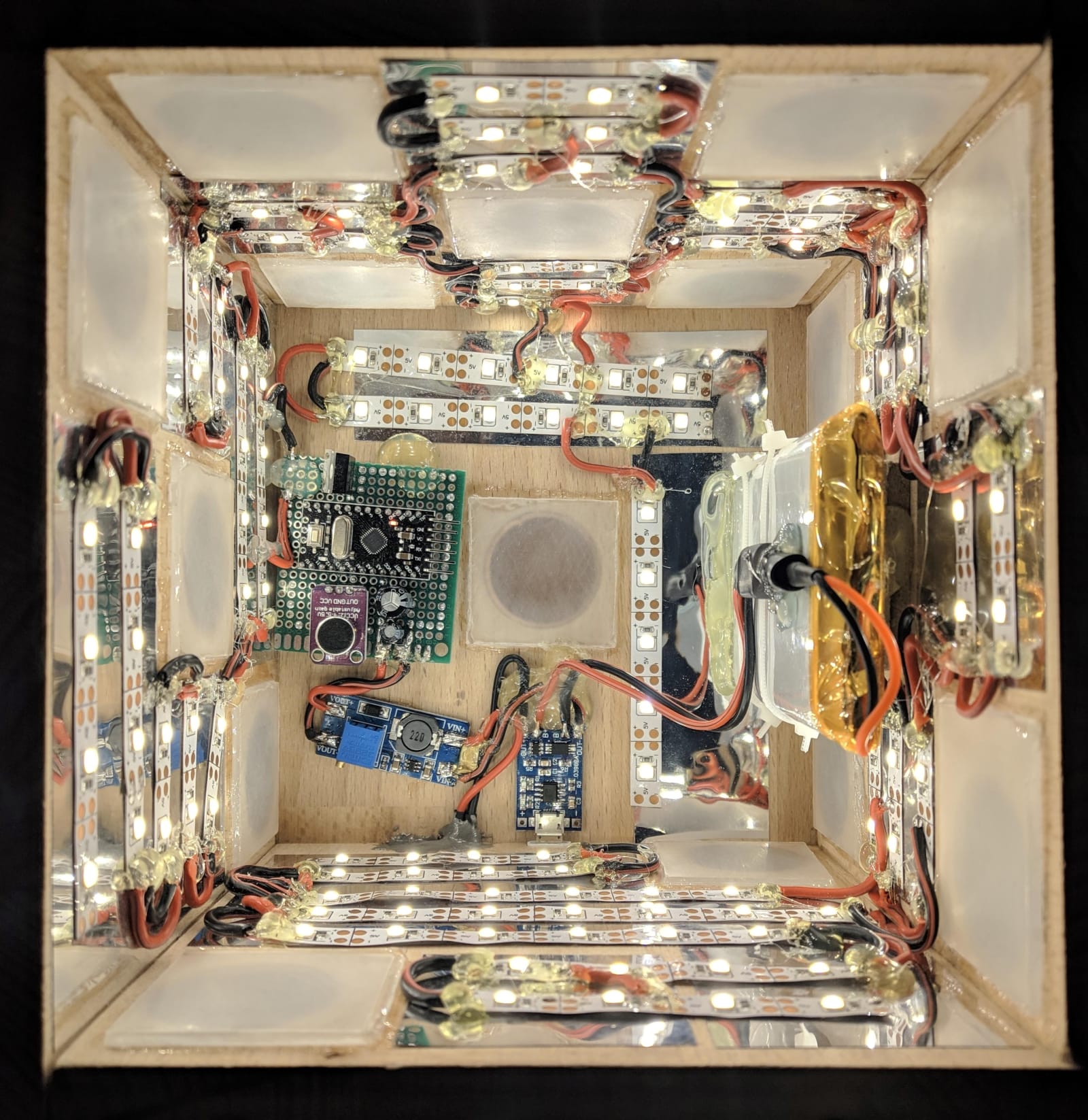
As I said, this was my first Arduino Project. I purchased an arduino pro mini and programmer from Aliexpress. I tried many different microphones and sensor to find the best one to detect knocks. I also bought a TP4056 lithium battery charger for cheap. It comes with a micro usb port, but I wanted type c because I like the idea of one connector on everything. So I also bought a micro usb to type c adapter. I needed LEDs, so I chose a 5V warm white strip and bought a 5v step up converter. To dim the LEDs I used N channel mosfet. I wired everything up, including a 10000 mah lithium polimer battery.
The Arduino Sketch
I am not a programmer, but thankfully the internet is full of arduino sketches you can look at to learn something. Basically, my program tells the microcontroller to listen on the analog pin if the voltage of the microphone exceeds a certain threshold. If the threshold is crossed, the Arduino registers the first “knock” and then listens for another peak in volage during the following 400ms. If the second “knock” is registered, the arduino fades up the led strip and starts listening again. It’s a very simple program but it works quite well, maybe because I used a good microphone and not the cheapest I could find on Aliexpress.
Problem I encountered and possible fixes
I am a perfectionist, and while I am incredibly satisfied with this light, there are some small imporvements I could make in the next iteration.
The main problem is that the battery is drained even when the LEDs are turned off. The arduino has a red LED that is always on, and the boost converter is always on, too. For the next light I will write better software to allow the Arduino to sleep. The boost converter circuit should also be turned off when not in use. That is why I included a switch that cuts power to the arduin and boost circuit, but I think it ruins the clean aesthetic of the cube.
The other problem related to the battery is that it lasts too little because the LEDs are too bright. I tried to enable PWM to fade them a little, but the frequency was picked up by the microphone that interpreted the noise as a “knock knoc”, shutting the dice down. I placed some capacitors near the micropone, to smooth the input voltage, but in the end I decided to make the LEDs run at full brighness. The light has been pretty stable, but I definitely need to improve both electronics and software in the next version.
There is no way to dim down the LEDs brightness, and the only user input it can register is a loud knock. The next version will be able to control LEDs individually, making it more flexible and the battery should last longer too. While I like the look of beechwood, I don’t like glulam. Because I had to cut the boards at 90°, you can see the endgrain at the top and bottom of the dice. The next version will be made of solid wood, with mitered corners that hide the endgrain.
Stay tuned for the next version!